|
|||||||
 |
 |
||||||
 |
|||||||
 |
|||||||
|
|||||||
|
|
||||||
|
|||||||
|
|||||||
|
Project Blade Runner Part 2Page 4
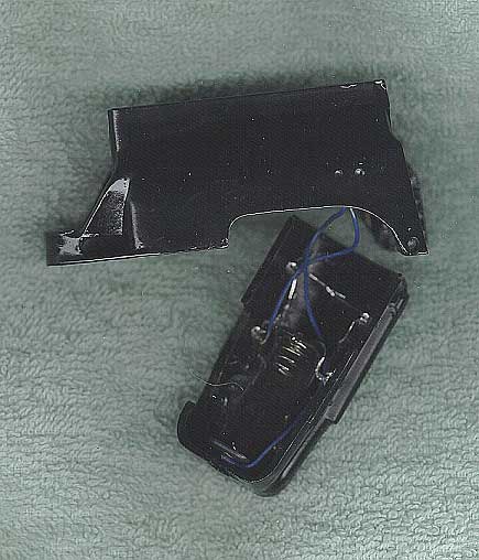
To
prepare the ammo clip, four red LEDs are installed, and their leads are soldered
together. In order to provide an adequate power supply, I trim an "N"
type battery holder to take the larger 7-volt battery that was selected, wire
up the assembly, and then glue it into the magazine.
Moving
our focus to the ammo housing, the DIP micro switch must be mounted inside next.
The switch is then wired to the ammo clip, and installing a battery to
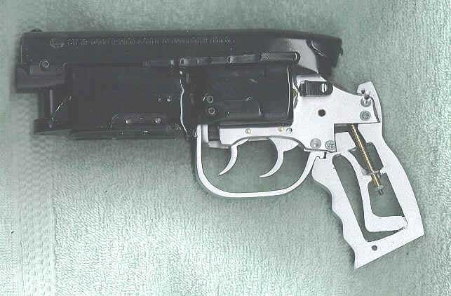
test the electronics, I then snap the ammo clip into the housing and mount the
assembly to the gun frame with one small Allen screw on the right side (just
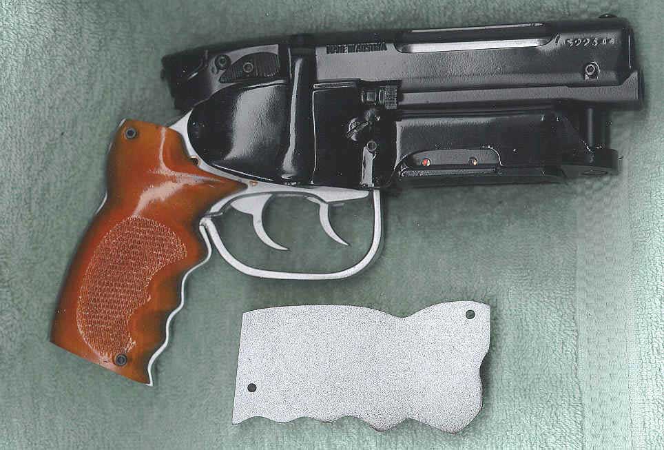
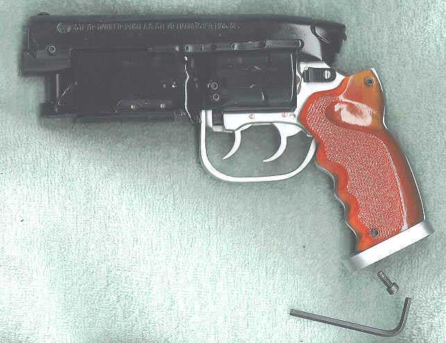
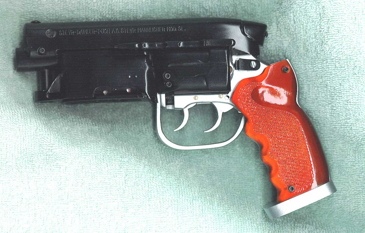
like the original, of course). The Bulldogs cylinder release knob is now mounted to the left side of the frame with a small screw. The next to last step is to mount the two pistol grips on the frame with four 4/40 Allen screws.
And there you have it, blade runners: the completed, fully detailed and functional blaster model ready to wreak havoc on all replicants!
Table Of Contents
|