|
|||||||
 |
 |
||||||
 |
|||||||
 |
|||||||
|
|||||||
|
|
||||||
|
|||||||
|
|||||||
|
Project Blade Runner Part 2Page TwoThe
barrel also gets a full painting run, plus one extra coat and a couple of coats
to the inside of the barrel.
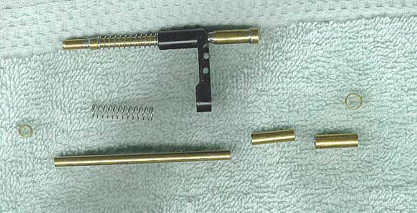
Next
on the milling setup, the aluminum tube made for the bolt is milled by cutting
off a section to make a C-shaped part; then with a special jig made to hold
this new part, I mill a slot in it for the sliding travel groove.
For
the hammer, the small lever return spring hole must be drilled by hand, and then
the spring, lever, and retaining pin are installed.
The hammer can then be pinned into the Bulldog frame using the special
piece of brass tubing fabricated for this purpose . For the trigger, the return spring hole must also
be drilled by hand, after which the spring is installed, and then the assembly
is mounted into the frame with its retaining pin. Next I install the pistol grip frame by fastening it with four screws -- two per side. With
the primary trigger and grip frame in place, the trigger guard can be installed
into its rear capture slot and then fastened with the cylinder swing arm to the
frame. A 4/40 Allen screw is used
to hold both. I
then assemble the hammer spring assembly.
The ball end is mounted onto 4/40 threaded
rod, which is cut to length, sheathed with a pre-cut brass tube, fitted with the
return spring, and fastened together with a washer and 4/44 nut. I test fire the weapon
a few times to make sure it works properly.
The front trigger is then installed with its brass
retaining pin. Taking
the tubing previously parted with the lathe, I solder these parts together to
form the cylinder's locking rod. Slipping
on the cylinder's swing arm and spring, I then solder a small piece of tubing
onto the assembly to hold the spring and arm together.
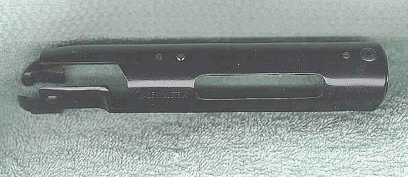
A quick trip to the belt sander results in smooth, beveled joints. After cutting a 3/4-inch length of 1/2-inch OD
aluminum tubing to create a barrel mount, I insert it into the Bulldog's fame
and then slide and glue the barrel onto it. Next,
a 6/32 button head Allen screw is cut to length and threaded into the tapped
front scope mounting hole of the Steyr receiver in order to form the front
sight, exactly like the original prop. The three remaining scope screw holes of
the Steyr are plugged with slotted set screws,
again to match the original. One of
these is a special screw -- slightly longer to allow it to lock into the bolt's
slot at the top for rotational travel control. The tiny tip-like projection of the Steyr receiver end cap is then glued into place, followed by insertion and gluing of the cap itself to plug the opening of the receiver above the Bulldog barrel. Table Of Contents
|