|
|||||||
 |
 |
||||||
 |
|||||||
 |
|||||||
|
|||||||
|
|
||||||
|
|||||||
|
|||||||
|
Project Blade RunnerPage FiveNext I turned down an aluminum cap to plug the moon-shaped
cavity in the end of the Steyr receiver where the original rifle barrel
threaded in, again copying the necessary details from the stunt prop.
I made this component a two-part assembly, with the small center
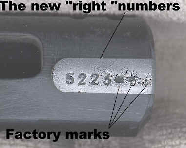
bead as a drop-in part. The final critical detail on the receiver was to
recreate the actual Steyr serial number from the original hero prop.
Our new casting obviously had a different serial number, so I milled
a slot into the "hero" receiver and then carefully sanded
and fitted a drop-in serial number plug from my best copy of the stunt
prop. Now that the Steyr receiver had been successfully mounted and the pistol frame details worked out, it was possible to finish fitting the side covers to the prototype. With the swing arm installed and the cylinder set in the proper position in the Bulldog's frame, I proceeded to fabricate a cylinder rod out of several pieces of brass tubing by soldering them together. The two side covers had to fit over the cylinder and allow it to turn while also matching the proper placement and shape of these parts relative to the stunt prop. It took many days to shape and carve these parts out. As I worked with the cylinder in the revolver, it
became apparent that a spring was needed to hold the cylinder latch
rod in place. This necessitated the addition of yet another ring
of cut tubing, which was soldered into place to hold the locking spring.
All in all five sections of tubing had to be spliced together
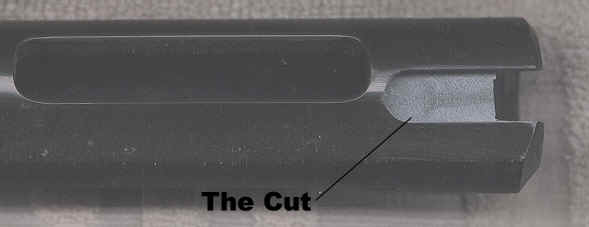
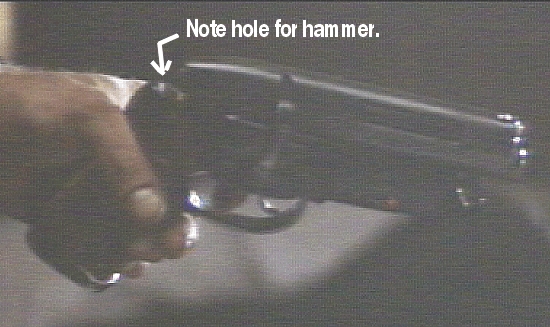
to make this one rod. Next came the working trigger and hammer.
From the stunt prop it was evident that the Steyr receiver had been
cut to fit around the revolver frame, including removal of a section
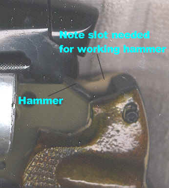
at the rear to allow the hammer to drop through. But it was also
evident that the Steyr's rear bolt cap was uncut, so the only solution
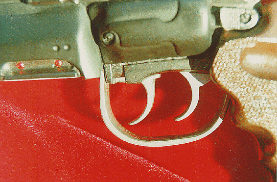
to fitting all the components was to "bob" the hammer.
Charter Arms did offer a factory bobbed hammer as an option, but the
factory piece is still too large. Either way, the propmaker had
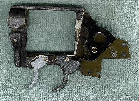
to cut down the Bulldogs hammer to spare the Using a cut away pistol frame, I studied the working of the trigger and hammer actions carefully to recreate them in the model. I found that the Bulldog hammer has a small spring loaded lever that the trigger pushes on to the throw the hammer back, and that for the trigger to return to the fire-ready position, it had to stroke by this lever to get below it again. This lever had to be able to allow the trigger to pass, and then it had to spring back in place so that the trigger could engage it again. Prototype testing demonstrated that the cast polyurethane was not strong enough to withstand this pressure when cast to the same dimensions as the steel part, so I was forced to both thicken this lever as much as possible and to recast it out of epoxy.
Table Of Contents
|