|
|||||||
 |
 |
||||||
 |
|||||||
 |
|||||||
|
|||||||
|
|
||||||
|
|||||||
|
|||||||
|
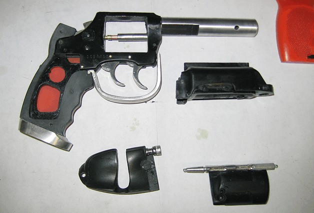
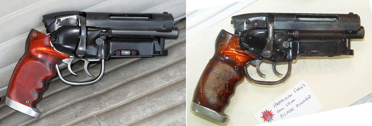
Rebuilding the Prop How much have I redone? More like what have I NOT reworked? ...and the easy answer is: the only part that did not get reworked is the cylinder. First, I want to state that I gave myself the mission to recreate the real prop gun, the WorldCon model inside and out as accurately as possible. This meant using real gun screws where needed and not changing anything if I could possibly avoid it and using real gun frames and parts unchanged from the real prop.
The earlier models also had this goal, i.e. to be as real as I could make them, serviceable like real guns, as in being able to tear them down with screwdrivers and so on.
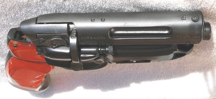
The new CS&T model was developed using an actual Charter Arms Bulldog revolver and a Steyr Rifle receiver to insure accuracy. This is how the propmakers built the original prop. This is how I kept true to the original dimensions with this replica display model. All of my models of the Blade Runner props are intended as Display Models, able to show the real working features and details of the real prop. They are NOT intended to be used as costume props, nor Movie, TV or stage props, and they are NOT TOYS. I have stunt models for those types of use. Okay, Public Service Announcement over, back to the current model: The bolt turns and retracts the pin in the front end cap of the Styer, so this pin had to be removed and made into a standalone part and mounted onto the bolt. I redrilled the hole in the front cap, and as the pin retracted I found I needed a longer front cap to hold the pin, so a new one was made.
Next, the scope mounting screws that are on top, using a picture of this receiver I aligned all three screws to match.
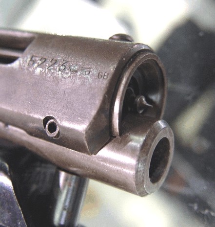
With the great photos from Karl I saw that the barrel was cut just so and I now had work hard to get the ends of my barrels just right.
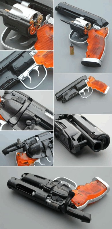
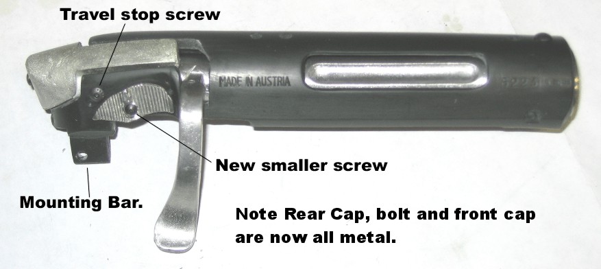
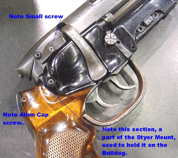
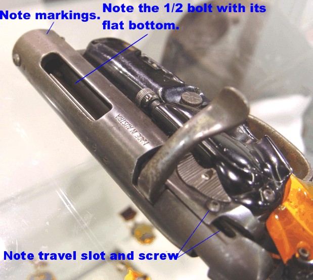
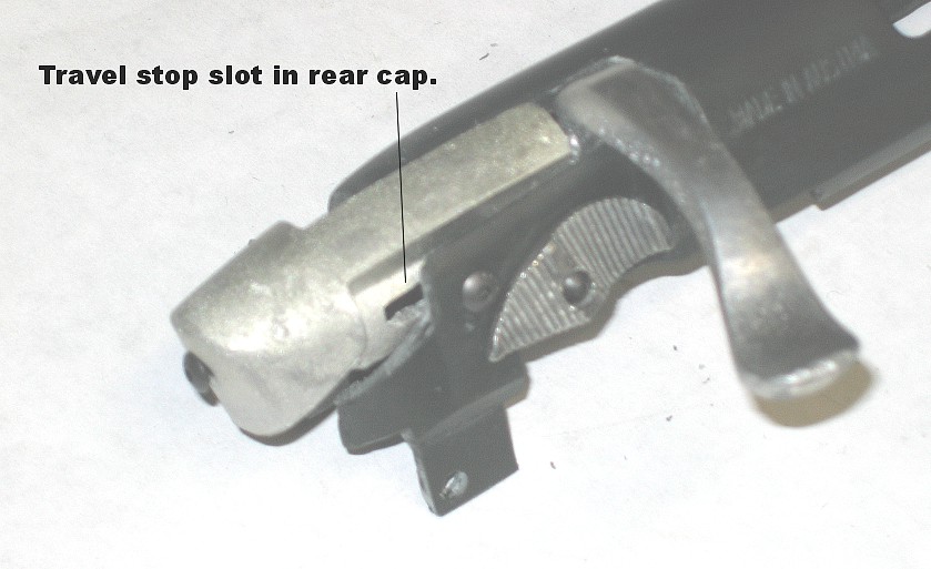
One major find was discovering HOW the receiver was held onto the Bulldog. Not my old idea of two rails and slots, and not by the extra side mounted screw, no, this “extra” round head screw on the side is the TRAVEL STOP for the bolt, it runs in a slot cut into the rear cover.
Picture by Richard Coyle It was held in place by a side bar down on the right side at the rear, a part not machined off and a leftover from the original mounting housing of the receiver. Most was cut away but one small bar was left, and it is held in place by being under the right cylinder cover and with that cover’s rear screw.
When I was first building the old C&S model I studied the stunt model I have and could find no clue as to how the rear of the Styer receiver was held on. I looked for screws like in the front, but no, and a pin would have worked, but there was no sign of one. I now know about the side bar, but on the stunt model this was covered up by filling clay to keep the rubber out of the real guns and thus hidden. So I came up with the idea that they could have machined in a pair of slots and added bars to the side of the Bulldog frame to hold the receiver onto the pistol frame. Thus, these are inside and invisible on the outside just like the stunt model. As discovered at the ‘ 06 WorldCon, the bolt was totally different from what had been thought. It is a 1/3 part of a round rod, flat on the underside AND turns with the cocking lever, (the real one does not do this), OPENING the injector port and thus the inside of the receiver, (why? No one knows…) and then can only retract about ¾ inch on the travel stop by the slot in its rear cap. This was a real bear to work out and model.
I went through about four or five tries to fit all of this together. The final model of the bolt was so thin I felt it would never last as a plastic part so I am thankfull I have a great new shop to do the castings in METAL.
I felt the same with the rear cap; with its now stock thin wall it too would not hold up well in plastic, so it too is now metal.
And with the first production run I found out that the metal casting system was not working well with the bolt, it was so long and with that large lever was coming out bent. While we were able to bend it back in place, I wanted a better system. We then went back and made the bolt and lever into a three part assembly, another reworking, an on-going process, to make a better model. On the old C&S I wanted to have a working bolt. It seemed very possible that the propmakers on the film had done so. For within the dropped gun scene, the fact that the cocking lever swung out was visible in the film. Not knowing then what they had done (see above) I tried to figure out how to do it. There were a few problems. The cocking lever turns on the bolt and then runs backward in slots inside the Styer receiver, molding this alone was a real problem. Next, the rear cap does not turn so it had to be held in place. I did that by making a “D” shaped pocket in the rear cap and a bar to fit it on the end of my bolt.
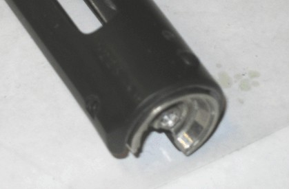
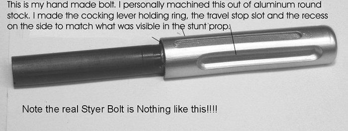
And if you look at a Styer receiver and its original bolt, then you can clearly see that they did NOT use a real bolt in the prop, and the real Styer bolt does not have a long notch cut into it. So I had to machine a new bolt. Next was the travel stop, for the bolt could not just pull out, so I machined a slot on top and used one of the rear screws as a travel stop. By careful planning, I stopped the bolt before the cocking lever cleared the rear of the Styer receiver and thus it was held in the proper position to be run in again. Last, of course, I had to machine all of the bottom away to clear and to sit on top of the Bulldog. With so much cutting I ended up with less than ½ of a round rod and so there was nothing to hold on the cocking lever. Because the front of the cocking lever wanted to twist in the bore I added a ring and slot in the bolt to help hold these two parts together. For the complete story of the first model see: http://www.racprops.com/issue4/projectbr_pt1/ http://www.racprops.com/issue4/projectbr_pt2/ And further reading on HOW it might function: http://www.racprops.com/issue4/brblaster/ Also Leon's gun: http://www.racprops.com/issue4/index.php And last back to the Blade Runner model: http://www.racprops.com/issue5/brblaster_take2/ Returning to the WorldCon gun: the real bolt (the prop) is a 1/3 round section and flat on the bottom and turns with the cocking lever, and pivots on the front pin and the screw in the rear cap. For this reason, the twisting of the bolt on the rear screw and the rear cap on the bolt is revealed from many angles. From these pictures you can see that the real cap is hollow. I needed a new real cap to be accurate, so I used an older real rear cap.
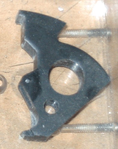
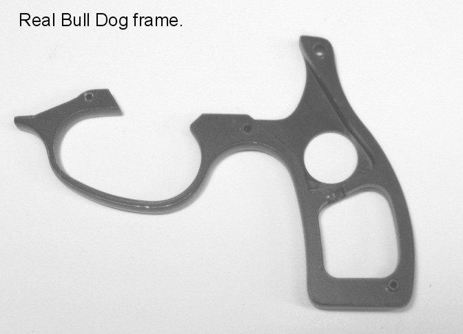
Next is the Bulldog pistol frame: on the old C&S I was trying to fit a full bolt on top. Since the original propmakers only planned to fire blanks on the set and never real rounds, they COULD have cut the top of the Bulldog’s frame down for more room and even milled a little off the side while they were at it and added side rails with pins for the slotted Styer receiver. And they might have wanted a little more holding action of the Bulldog to the new pistol frame and added a few extra screws.
Well, pictures don’t lie, and I can see that they did none of the above. I needed to go back to a more stock Bulldog frame.
I made a new mold master from a second Bulldog frame, this time keeping it as stock as possible. Only two holes were drilled, NO cutting of the top frame, no trimming and no side ribs to hold the Styer receiver. So it was out with the extra screws and, in fact, I am buying the Charter Arms FACTORY SCREWS for the grip frame, hammer, thumb release and the push out pin. I am doing a working thumb release system on this model as well, so the cylinder can be opened without removing the ammo housing. When I had interviewed the propmaster, he said they removed the ammo housing to reload, this why my older models did not have this feature. Creating
an opening cylinder (without needing to remove the Steyr rifle ammo
magazine)
was accomplished by cutting off the rod that supports the ejector
"star" (the mechanism that lifts the empty shell casings from the
cylinder). This is something that would be impractical on a real
revolver as you
would have to push out the brass shell casings manually, one at a time,
instead
of simply pushing on the ejector rod.
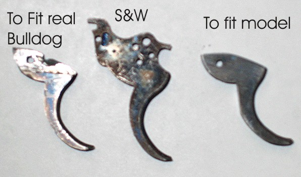
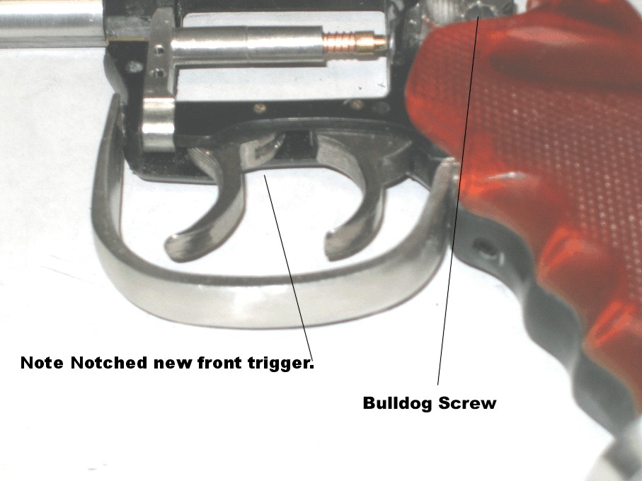
Triggers: the Worldcon pictures revealed that the front trigger was not a second Bulldog trigger. Thanks to Craig Kovich who found the 40’s S&W 38 Revolver trigger, so we now have the correct front trigger.
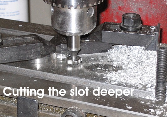
But these triggers needed to be cut and machined to fit in the Bulldog frame and even then I spotted that the back of the trigger was machined flatter than the actual trigger, and the slot in back needed to be deeper so I milled them as well. Placing it correctly in the Bulldog frame was equally technical.
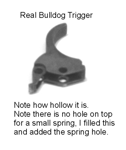
I have also replaced my old trigger to a more correctly fitting Bulldog trigger.
The hammer has been redone with a little more metal and the top less bobbed, leaving a section of the upper part of the hammer which I believe is part of the hammer drop/firing pin safety system.
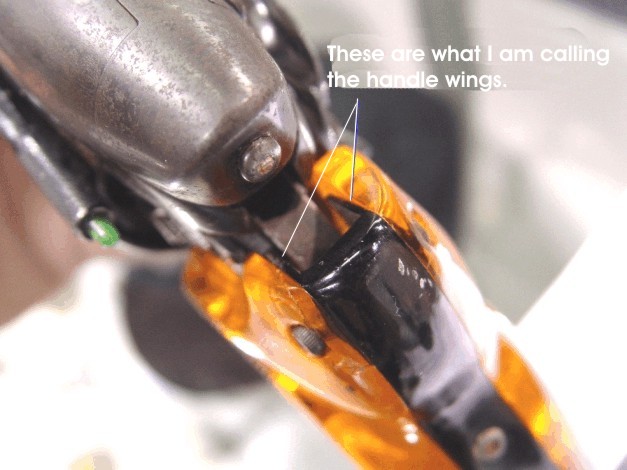
The Bulldog pistol grip frame is now cast as standalone totally stock part and the custom outer cover is added, as it is was with the real prop. It also has the hole showing the inner frame and the added side rails along the top; you can see them when you look down into the pocket for the hammer in the pictures. (The old C&S had these two pistol grip frames parts cast as one and no wings.)
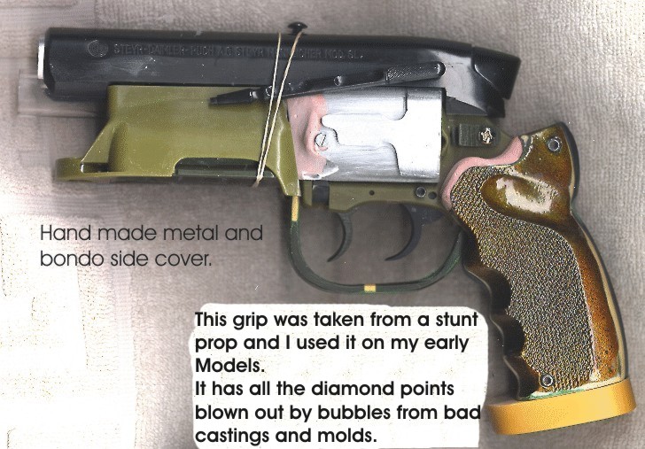
The Butt plate has been reshaped and thickened. 4/40 Screws are now used to hold it and there is NO cut out recess on the bottom. Turns out that was only a scratch in the paint on the bottom that, in the stills, hinted at the edge of a recess. An aside here; with the old C&S I made the side covers by cutting aluminum tubing to clear the Bulldog’s cylinder, then I sculpted the detailing using a second tube and bondo and plastic. Remember, NO ONE had the real gun and no one had covers made to clear the cylinder, so I hand made them myself.
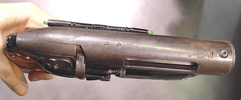
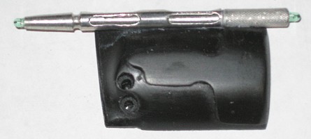
A new hollow side rod has been made to allow wires to run to both ends for the LEDs. This led to making a new larger rear knurled rod as well. It also had to be made hollow to allow wires for the green LEDs. We still believe the original part on the prop was made out of an old jeweler’s screw driver.
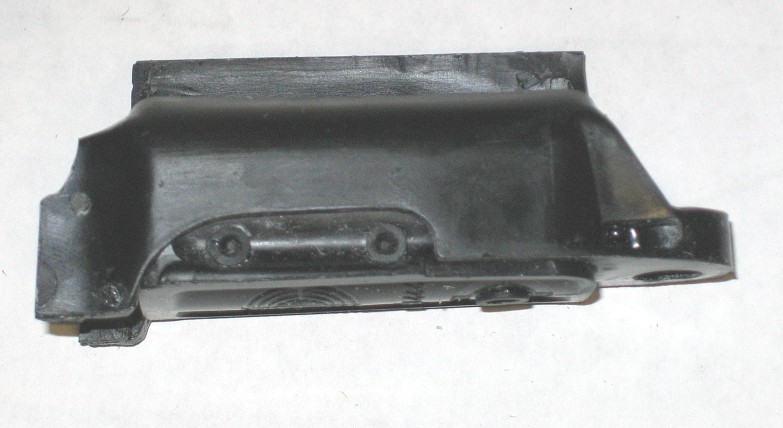
I can confirm this rod was mounted on the side cover, not the Styer Receiver.. Again due to the pictures, we could see detailing never before seen: the ammo housing has a ½ moon mark. Another new master ammo housing part had to be made while leaving intact the normal molding and parting lines of a real Styer Ammo Housing.
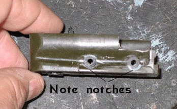
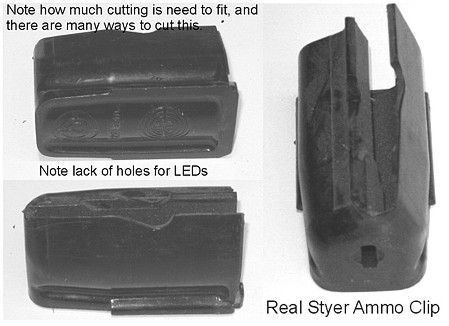
The old ammo clip was close, but in the pictures I could see that to add the LEDs and their mounting holders, the original builder had NOTCHED the lower rails to fit these parts in, so using another new ammo clip I did the same.
By the way there is a fair amount of cutting on the ammo housing and ammo clip to fit them under the Bulldog's barrel.
Picture by Richard Coyle The safety switch on the side of the Styer receiver turned out to have a smaller round head screw than I had been using, so that was also corrected. I am using small rod to hold the triggers and the pistol frame. These are the same size a real Bulldog uses. A friend found a Weaver Scope and let me have one of the knobs (Thanks Josh), so I made metal castings of it.
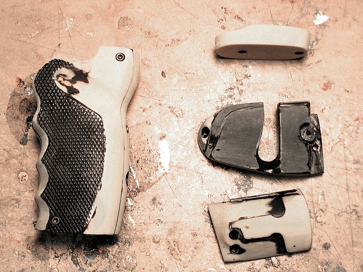
I hunted for the switch that was between the LEDs but could not find one, so I Photoshopped the switch cover and made a printout that would fill in and reworked the ammo clip to hold a newer switch with a very close look and cream-colored toggle. Mold boxes and molds had to be made. Each part had to be laid into a clay bed, sculpted to control the parting lines and mold keys set to hold the two part molds in place. Test castings were made and changes made to correct any problems the tests revealed. Some models had to be reworked and laid into clay a second time, all this before I was ready to start production.
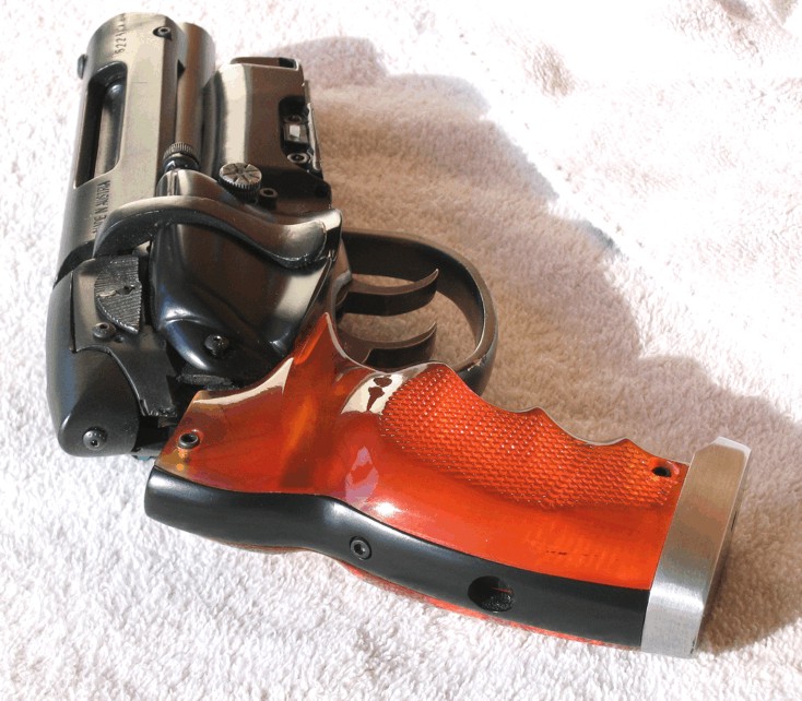
My first release showed that I had misread the size of the pistol grips, so I halted production and redid them, and then shipped the first 15. (I had worked from a stunt casting taken from the set, but somewhere, before I got it, the grips ended up short, compressed during an earlier casting run. Either the original stunt models were short or the copies made later on were…these grips looked correct until matched up to the real gun.)
Sadly, even this second try was still off. Again I had not gotten these grips right, so I redid them again and again until I got them as right as I could. The two side covers have been reworked. The right side has been cut out to show the cylinder and been reshaped, and the left side now has a groove on the inside to hide the power wires to the rod LEDs and a relocated screw hole, and I shortened the body.
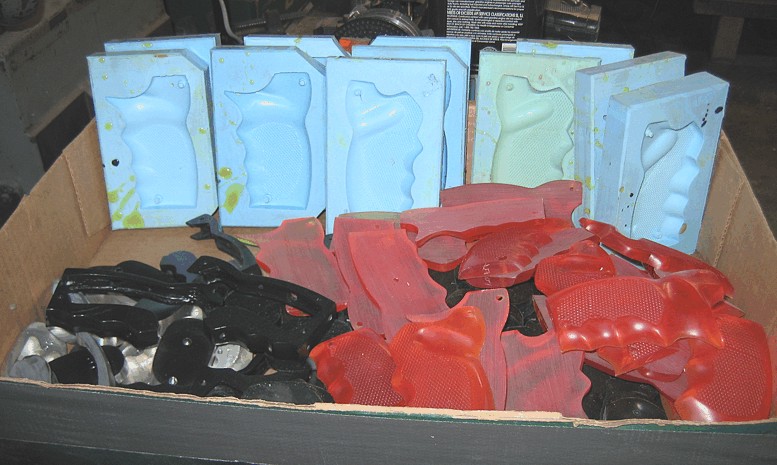
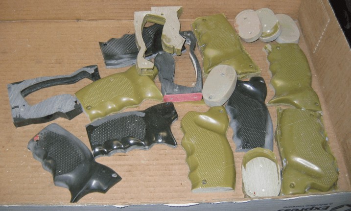
Note, the above are works in progress, being wet sanded after painting. One small thing, due to the fact I am trying to recreate the prop exactly as it was and is nowadays, right down to the smallest detail there is one thing that has shown up with the plastic model: flexing. All this metal and plastic and using the real mounting screws and pins of the real pistol to the pistol grip frame, allow some flexing. If you wave the model around you will feel some give. This should not be a problem with the All Metal Model. This project has taken a lot of tries and refitting and work and a bunch of rejects to get those grips as close as I now have them. How many?? How's this? A tray of rejected molds and parts:
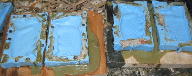
To stretch the grips I placed the molds in bondage:
I would stretch them a little and power drive a screw into the mold, then pull and stretch it some more and drive in another screw. How many tries did it take to sculpt them? Many more than pictured here:
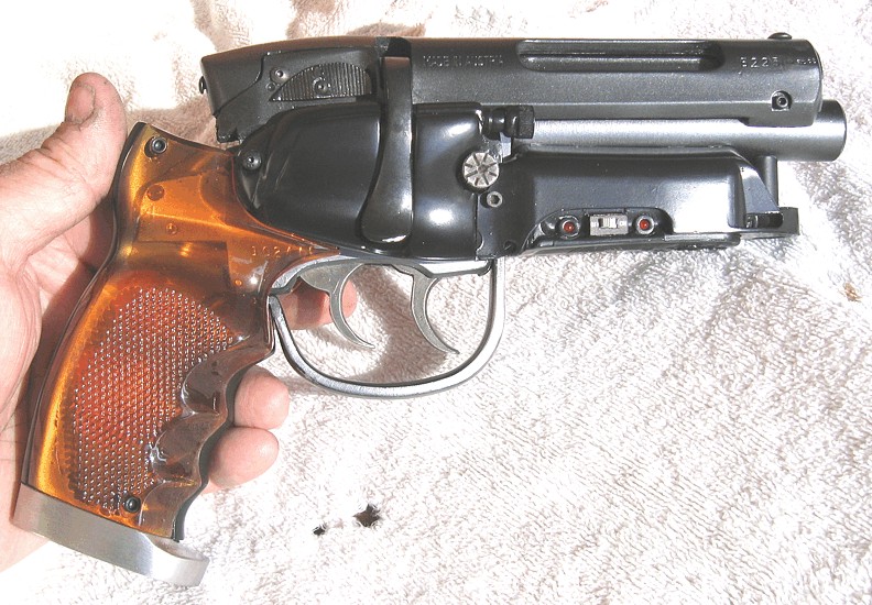
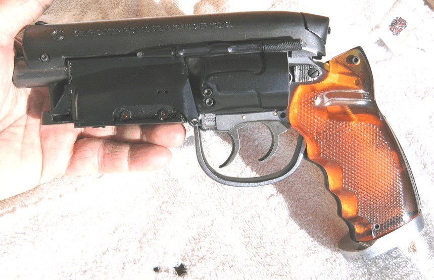
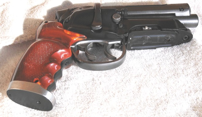
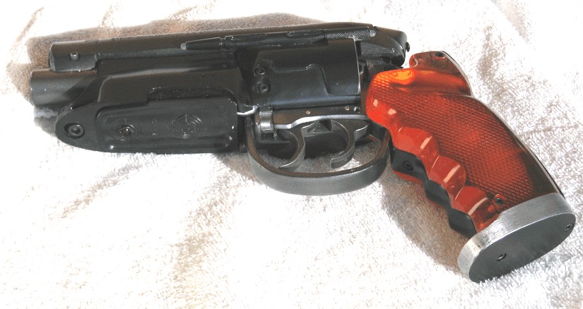
And there you have it, the Super Detailed WorldCon Blade Runner C, S&T Blaster. This IS the Latest model with the new grips.
I started work on this new model within a month of my WorldCon visit. I had to set it aside a few times to pay bills but even so I probably have about six full time months of real hard work in it. I wanted to get it accurate right out of the gate. No versions twos or threes, just a version one. So that is from August 26, 2006 to April 13, 2007, some eight months later. And we have been working the metal parts at the same time, reworking and reworking what would not work in metal until itc finally did. So I have been building two models at the same time. If I could have known just how much time and money this was going to cost me I might have thought twice. This is my MAGNUM OPUS. The new name is CS&T WorldCon Model. (C= Richard Coyle, (Builder) S= Phil Steinschneider (Researcher old model) And T= Karl Tate for finding and sharing the WorldCon Blaster) Table
Of Contents
|